
How to Inspect and Test Furniture Connector Quality

How to Inspect and Test Furniture Connector Quality
Furniture connectors are small components, but a defective or incompatible fitting can affect an entire cabinet, wardrobe or flat-pack furniture order.
Common quality problems include:
- Cam locks that crack during tightening
- Bolts that do not engage the cam
- Incorrect dimensions
- Damaged threads
- Uneven surface finish
- Plastic connectors that deform during insertion
- Joints that remain open
- Fasteners that pull out of the panel
- Connectors that cannot withstand repeated assembly
A reliable quality-control system must examine the individual components and the finished furniture joint.
Quick Answer
Furniture connector inspection should include:
- Product and batch identification
- Visual inspection
- Dimensional measurement
- Cam-and-bolt compatibility
- Thread and tool-drive inspection
- Surface-finish evaluation
- Installation-force or torque checks
- Assembly trials using the actual panel
- Joint opening, tensile or pull-out testing
- Shear and racking evaluation
- Repeated assembly when required
- Packaging and traceability checks
There is no universal acceptable pull-out force, torque or cycle count for every connector. The acceptance criteria should be defined from the furniture design, panel material, connector specification and intended use.

1. Start with an Approved Specification
QC cannot decide whether a connector is correct without a reference specification.
The purchase document should identify:
- Product number
- Connector type
- Material
- Finish
- Dimensions
- Compatible components
- Panel material
- Panel thickness
- Drilling pattern
- Installation method
- Packaging quantity
- Performance requirements
- Approved sample or drawing revision
Terms such as “15 mm cam” or “furniture bolt” are not complete specifications.
For example, nominally similar cam housings may use different heights, bolt heads, drilling depths and bolt-hole diameters.
2. Verify Product and Batch Identification
Before opening the cartons, confirm:
- Supplier
- Purchase order
- Product code
- Drawing revision
- Material and finish
- Quantity
- Production batch
- Manufacturing date, when provided
- Carton number
- Component combination
Do not mix visually similar cams, bolts or dowels before verifying their labels.
Batch traceability allows the factory to identify affected furniture if a problem appears after assembly.
3. Inspect the Packaging
Packaging should protect the connectors from:
- Moisture
- Contamination
- Scratching
- Impact
- Deformation
- Mixed components
- Quantity loss
Check for:
- Wet or crushed cartons
- Broken bags
- Rust staining
- Oil leakage
- Mixed labels
- Missing batch codes
- Damaged internal boxes
- Loose parts in the carton
- Incorrect quantity per bag
For 3-in-1 connector sets, verify that each package contains the correct ratio of:
- Cams
- Connecting bolts
- Alignment dowels
A complete order quantity is still unusable if one component is missing.

4. Visual Inspection of Cam Fittings
Zinc-Alloy Cams
Look for:
- Cracks
- Incomplete casting
- Cold-shut or unfilled areas
- Excessive flash
- Burrs
- Porosity visible at the surface
- Distorted internal profile
- Damaged tool drive
- Missing direction mark
- Broken rim
- Uneven finish
A cam may appear acceptable from the outside while its internal bolt-engagement profile is incomplete.
Inspect samples from multiple cartons and positions within the shipment.
Steel Cams
Check for:
- Deformation
- Sharp edges
- Cracks
- Incorrect forming
- Damaged drive
- Uneven plating
- Rust
- Burrs around the bolt opening
- Incorrect cam profile
Functional Orientation
Verify that the direction arrow, entry mark or opening corresponds with the actual bolt-entry direction.
An incorrect or unclear mark can create assembly complaints even when the fitting is dimensionally correct.
5. Visual Inspection of Connecting Bolts
Check each sampled bolt for:
- Straightness
- Correct overall length
- Complete thread
- Damaged thread
- Head shape
- Head diameter
- Head thickness
- Neck dimensions
- Tool-drive quality
- Burrs
- Cracks
- Uneven coating
- Rust
- Contamination
Roll the bolt on a flat reference surface if bending is suspected.
A slightly bent bolt may install into the panel but enter the cam at an angle and prevent smooth locking.
6. Visual Inspection of Plastic Connectors
For plastic connectors and sleeves, inspect for:
- Flash
- Short moulding
- Sink marks
- Warping
- Cracks
- Discolouration
- Contamination
- Blocked holes
- Damaged locking features
- Uneven ribs
- Brittle appearance
- Mixed material or colour
Visual inspection cannot prove plastic formulation, but it can identify moulding defects and abnormal production variation.
Functional testing should verify that the connector does not crack or permanently deform during correct installation.
7. Measure Critical Dimensions
The inspection drawing should identify which dimensions affect function.
Cam Dimensions
Measure:
- Outer diameter
- Height
- Rim diameter
- Rim thickness
- Bolt-entry position
- Internal engagement location
- Tool-drive dimensions
Bolt Dimensions
Measure:
- Overall length
- Threaded length
- Thread diameter
- Head diameter
- Head thickness
- Neck length
- Shank diameter
- Drive dimensions
Dowel Dimensions
Measure:
- Diameter
- Length
- Rib dimensions
- Expansion section
- Shoulder position
- Straightness
Plastic Connector Dimensions
Measure:
- Overall length
- Outer diameter
- Locking features
- Flange size
- Insertion section
- Hole dimensions
Use calibrated equipment suitable for the required tolerance. Depending on the feature, this may include:
- Vernier caliper
- Micrometer
- Height gauge
- Optical comparator
- Thread gauge
- Pin gauge
- Go/no-go fixture
- Profile measurement equipment
8. Do Not Measure Only the Outer Diameter
A 15 mm cam may pass an outer-diameter inspection and still fail because of:
- Incorrect height
- Wrong internal profile
- Incorrect bolt-entry level
- Excessive internal flash
- Wrong drive geometry
- Incompatible bolt head
Dimensional inspection should focus on functional relationships rather than one easy-to-measure dimension.
9. Use Go/No-Go Functional Gauges
For high-volume inspection, a dedicated gauge can quickly verify whether a component fits within an approved range.
Possible gauges include:
- Cam-hole insertion gauge
- Approved reference bolt
- Bolt-head entry gauge
- Thread gauge
- Bolt-projection fixture
- Dowel insertion fixture
- Complete connector test block
A go/no-go gauge should be made from the approved product drawing and maintained as inspection equipment.
It should not replace periodic dimensional measurement or complete assembly tests.
10. Check Cam-and-Bolt Compatibility
The most important functional inspection is whether the cam and bolt work together.
Confirm that:
- The bolt head enters the cam.
- The cam begins engagement at the correct position.
- Rotation pulls the bolt inward.
- The movement is smooth.
- The cam reaches its locking position.
- The cam does not crack or slip.
- The bolt can be released if the system is detachable.
Do not test a new batch only with a random bolt from the same shipment. Also compare it with:
- Approved master bolt
- Approved master cam
- Current production components
- Customer-provided reference parts, where applicable
This helps distinguish whether a problem comes from the cam, bolt or both.
11. Inspect the Thread
Thread quality affects installation and pull-out performance.
Check:
- Thread diameter
- Thread pitch
- Thread depth
- Thread length
- Start of thread
- End condition
- Burrs
- Missing or flattened threads
- Coating buildup
- Compatibility with an insert or panel hole
For bolts installed directly into wood-based panels, evaluate the thread with the actual panel and pilot hole.
A thread that looks sharp may still be unsuitable for the intended substrate.
12. Inspect the Tool Drive
Cam and bolt drives must accept the specified assembly tool.
Check:
- Drive shape
- Drive depth
- Tool fit
- Slipping
- Rounding
- Burrs
- Off-centre forming
Conduct several installation cycles with the actual screwdriver or bit used in production.
Poor drive geometry can cause:
- Bit slippage
- Worker injury
- Incomplete tightening
- Surface scratching
- Damaged fittings
- Assembly-line delays
13. Evaluate Surface Finish
Surface finish may provide:
- Appearance
- Corrosion protection
- Reduced installation friction
- Compatibility with customer requirements
Inspect for:
- Uneven colour
- Bare areas
- Peeling
- Blisters
- Burn marks
- Roughness
- Staining
- Rust
- Excessive coating buildup
- Finish inside functional areas
A thick or uneven finish can change dimensions and interfere with cam rotation or thread fit.
Colour alone cannot confirm coating type or thickness. If coating performance is important, define an appropriate supplier declaration or test method in the specification.
14. Installation-Force Testing
Plastic dowels, sleeves and press-fit connectors require controlled insertion.
Record:
- Pilot-hole diameter
- Panel material
- Panel thickness
- Insertion method
- Maximum force
- Final seating position
- Visible damage
- Connector deformation
Insertion force that is too high may cause panel splitting. Force that is too low may indicate an oversized hole or undersized connector.
The acceptable range must be established through approved samples and functional testing.
15. Installation-Torque Testing
For screws, bolts and cam fittings, measure or control the torque required during installation.
Possible observations include:
- Torque needed to install the bolt
- Torque at which the joint closes
- Torque at which the cam is damaged
- Torque at which the panel thread strips
- Difference between samples
- Difference between panel batches
Do not use destructive torque as the normal production setting.
A safe production setting should provide reliable assembly while remaining below the level that damages the connector or panel.
16. Complete Joint Assembly Test
This is the most important production test.
Use the actual:
- Panel supplier and grade
- Panel thickness
- Drilling programme
- Cam
- Bolt
- Dowel
- Assembly tool
- Operator method
Inspect:
- Ease of assembly
- Panel alignment
- Joint closure
- Cam rotation
- Required torque
- Surface damage
- Cam seating
- Bolt engagement
- Dowel fit
- Ability to disassemble, when required
The connector and furniture must be treated as one system.
17. Tensile or Joint-Opening Test
A tensile test applies force that attempts to pull the joined panels apart.
It can evaluate:
- Cam engagement
- Bolt pull-out
- Panel failure
- Connector deformation
- Joint opening
- Failure location
Record:
- Panel material and batch
- Connector quantity
- Hole pattern
- Load direction
- Loading rate
- Maximum load
- Joint movement
- Failure mode
Do not record only the highest force. The failure mode provides important information.
Possible failures include:
- Cam fracture
- Bolt-head failure
- Bolt pull-out
- Panel breakout
- Cam-hole damage
- Joint opening without complete failure
18. Shear Test
A shear test applies force parallel to the joint.
This is different from pulling the panels directly apart.
Shear performance may depend on:
- Alignment dowels
- Connector position
- Panel edge quality
- Number of connectors
- Rear-panel construction
- Furniture geometry
Published connector data illustrates that tensile and shear results can differ significantly and vary between particleboard, MDF and solid wood. Lamello, for example, reports separate tensile and shear results by substrate for its individual connector systems. Those product-specific numbers should not be transferred to another connector.
19. Furniture-Level Racking Test
A connector can perform well in a small test block but still produce an unstable cabinet.
A furniture-level racking test examines how the assembled cabinet responds to sideways deformation.
Performance may be influenced by:
- Connector locations
- Rear panel
- Number of fixed shelves
- Panel thickness
- Cabinet width and height
- Joint clearance
- Base and wall fixing
- Assembly accuracy
Component pull-out testing and completed-furniture testing serve different purposes. One should not automatically replace the other.
20. Repeated Assembly Test
For knock-down furniture, test the required number of assembly and disassembly cycles.
After each cycle, inspect:
- Cam drive
- Internal cam profile
- Bolt head
- Bolt thread
- Panel hole
- Insert
- Joint gap
- Assembly torque
- Alignment
Possible results include:
- Bolt hole becoming loose
- Cam drive rounding
- Cam no longer pulling the joint closed
- Plastic sleeve damage
- Panel material breaking away
- Increasing joint movement
Do not claim unlimited reusability unless it has been demonstrated for the complete system.
21. Environmental and Storage Evaluation
If the furniture will be used or shipped in demanding conditions, consider whether the project requires evaluation for:
- High humidity
- Condensation
- Temperature changes
- Coastal environments
- Long sea transport
- Bathroom use
- Kitchen use
- Chemical-cleaning exposure
Check for:
- Rust
- Coating deterioration
- Plastic deformation
- Panel swelling
- Change in installation torque
- Reduced joint performance
Test conditions and acceptance limits should be agreed for the project. Do not apply one corrosion duration or environmental test to every furniture connector.
22. Sampling Plan
Inspection quantity should reflect:
- Order size
- Product risk
- Connector complexity
- Supplier history
- New or repeat order
- New tooling
- New material batch
- Customer requirements
- Consequence of failure
Increase inspection when:
- The supplier changes tooling
- A new subcontractor is used
- Material or coating changes
- Dimensions approach tolerance limits
- Mixed components are found
- Assembly complaints increase
- The panel specification changes
A small shipment of a safety-critical connector may require more attention than a larger order of a non-structural plastic cover.
23. Retain Reference Samples
Keep:
- Approved master sample
- Current production sample
- Samples from important batches
- Dimensioned drawing
- Inspection report
- Assembly-test panel
- Test photographs
Label each retained sample with:
- Product code
- Supplier
- Batch
- Date
- Purchase order
- Inspection status
Do not allow master samples to become mixed with production stock.
24. Common Defects and Their Effects
|
Defect |
Possible effect |
|
Cam diameter too large |
Difficult insertion or panel damage |
|
Cam diameter too small |
Loose fit and unstable orientation |
|
Incorrect cam height |
Wrong bolt alignment or surface breakthrough |
|
Internal casting flash |
Bolt cannot enter or cam cannot rotate |
|
Cam crack |
Failure during tightening |
|
Bolt too short |
Cam cannot capture the head |
|
Bolt too long |
Panels cannot close |
|
Bent bolt |
Angled entry and poor engagement |
|
Damaged thread |
High torque or weak holding |
|
Oversized plastic connector |
Panel splitting |
|
Undersized plastic connector |
Loose insertion |
|
Uneven coating |
Poor appearance or dimensional interference |
|
Wrong components packed together |
Assembly failure |
|
Missing batch identification |
Poor traceability |
25. Failure Analysis
When a connector fails, preserve the complete evidence.
Record:
- Product and batch
- Panel material and batch
- Hole dimensions
- Connector position
- Assembly tool
- Torque setting
- Number of assembly cycles
- Load direction
- Environmental exposure
- Photographs
- Failure surface
- Quantity affected
Avoid reporting only “cam broken” or “connector weak.”
Determine whether the failure occurred in:
- Connector
- Bolt
- Thread
- Plastic sleeve
- Panel
- Drilled hole
- Installation process
- Overall furniture design

26. Furniture Connector QC Checklist
Documentation
- Correct product code
- Approved drawing
- Correct revision
- Batch identification
- Material and finish
- Packaging specification
Visual Inspection
- No cracks
- No excessive burrs
- No deformation
- Complete casting or moulding
- Correct tool drive
- Complete thread
- Acceptable finish
Dimensional Inspection
- Cam diameter and height
- Bolt length and head
- Thread dimensions
- Dowel size
- Connector profile
- Functional-hole position
Functional Inspection
- Cam and bolt engage
- Smooth rotation
- Correct pulling action
- Correct insertion
- Correct tool fit
- Complete joint closes
Performance Testing
- Installation torque
- Tensile or pull-out
- Shear
- Racking where relevant
- Repeated assembly
- Environmental evaluation where required
Packaging
- Correct quantity
- Correct component ratio
- No mixed parts
- Clear labels
- Batch traceability
- Protection from moisture and damage
27. Information to Include in an RFQ
Provide:
- Connector drawing
- Panel material
- Panel thickness
- Joint configuration
- Drilling pattern
- Material and finish
- Compatible component details
- Quantity
- Packaging format
- Installation method
- Torque requirement
- Performance requirement
- Assembly-cycle requirement
- Application environment
- Inspection and sample requirements
If a customer requires a specific test result, the test setup must also be defined. A load value without the panel, direction and method is not meaningful.
Frequently Asked Questions
Can connector quality be checked without a panel test?
Dimensions and visible defects can be checked, but functional holding performance requires the actual panel and drilling system.
Is a heavier cam lock always stronger?
No. Weight alone does not confirm material quality, internal geometry, compatibility or joint performance.
Can we test only the cam and ignore the bolt?
No. Cam locks operate as a coordinated system. The cam, bolt, panel and drilling pattern must be tested together.
What is the most important cam-lock dimension?
Several dimensions are critical, including cam diameter, height, bolt-entry position, bolt-head geometry and bolt projection. No single measurement approves the system.
Should every batch receive a pull-out test?
That depends on risk, order history and the agreed control plan. Every batch should at least remain traceable and receive appropriate incoming and functional inspection.
Why does the same connector produce different test results in MDF and particleboard?
The substrates have different density and internal structure. Failure may occur in the panel rather than the connector.
How many times should a connector be assembled?
Use the number of cycles required by the furniture application. There is no universal cycle count for every product.
Does good plating guarantee connector quality?
No. Finish is only one quality factor. Dimensions, material, internal profile and joint performance must also be checked.
Conclusion
Furniture connector quality has three levels:
- The component must meet its drawing.
- The components must work together.
- The complete joint must perform in the actual furniture panel.
The most reliable quality-control process is:
Visual inspection + dimensional inspection + compatibility check + actual-panel assembly + project-specific performance testing
A cam or bolt should never be approved only because it looks similar to the previous product.
Related Haits Furniture Connectors


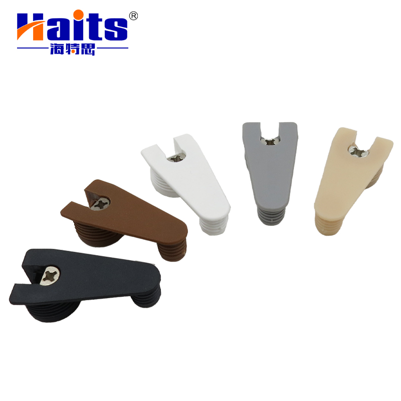


Zinc Alloy vs Steel vs Plastic Furniture Connectors
How to Choose Furniture Connectors for Particleboard, MDF, Plywood and Solid Wood


